3.3 Environment Sensor
-
Have you ever been in a greenhouse? Greenhouses are just one exampled of a monitored environment for growing plants.
Most plants and crops grow best in specific conditions. Greenhouses and other growing environments try to keep the temperature, humidity, light, and moisture levels at amounts that will help their plants to grow to be the biggest and best they can be.
In this lesson we are going to create an environment sensor that will detect each of these levels, and will alert you if the environment changes and is no longer in its optimal state.
-
The Challenge
- When you press the A button, the current humidity level will show on the micro:bit display.
- When you press the B button, the current temperature will show on the micro:bit display.
Required Devices
- 1 micro:bit
- 1 sensor:bit
- 1 DHT11 Temperature & Humidity Sensor
Suggested Blocks
- show number
- on button pressed
- query DHT11
- read temperature
- read humidity
- last query successful?
- set [variable] to
- [variable name]
Bonus Challenges
- If you change the string label of the “Humidity” and “Temperature” values to musical tones or melodies, can you play the tones each time the values are shown?
- Can you set the micro:bit to continuously update the values, and use the show leds block to ahow these constant updates on the micro:bit display?
Hints
- You will need to install the DHT11 extension to complete this challenge.
- Make sure that the pin number on the Query DHT11 block is the same pin number that your sensor is connected to.
- When using this block, make sure that you have the DHT11 selected (the DHT22 is a different sensor that we don't use).
- Also make sure that the "Pin Pull Up" has true selected, or the information from the sensor won't be read.
- When you press the A button, the current humidity level will show on the micro:bit display.
-

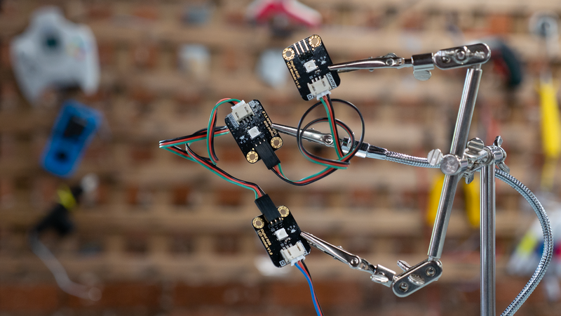
In this project we will need to connect multiple RGB LEDs together. In computational terms, this process is called: daisy-chaining (like the process of threading daisy flowers together by their stems).
Just like a real chain of daisies, we're going to connect each RGB LED to the next one in a chain. We'll then connect one end of the chain to the micro:bit. All three of the LED lights will receive electrical power from the one end that is connected to the micro:bit.
By connecting multiple lights together, we also only use one pin input on the sensor:bit, which frees up the other pins for use by other devices.
-

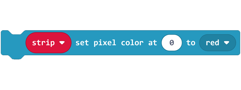
In this lesson we will need to install the NeoPixel extension once again and use some of those code blocks to control our RGB LEDs. For this lesson, we'll need a new block: strip set pixel colour.
This code block, used together with the
set strip to neopixel block, allows us to “daisy-chain” multiple RGB LEDs together and control the colours that each one emits. -
The Challenge
- Connect 3 RGB LEDs together in a daisy-chain.
- When you press the A Button the first light turns red, the second light turns green, the third light turns blue.
- When you press the B Button, the lights all turn a random colour.
- When you touch the logo, all the lights turn off.
Required Devices
- 1 micro:bit
- 1 sensor:bit
- 3 digital RGB LEDs
Suggested Blocks
- on button pressed
- on logo pressed
- pick random “0” to “255”
- set strip to neopixel
- strip show colour
- strip show
- strip set pixel colour
Hints
- You will need to install the NeoPixel extension to complete this challenge.
- When you daisy-chain LEDs, the first LED is the one that is plugged directly into the micro:bit. Count from there to the end of the chain to give each LED a number. Remember the micro:bit counts from 0, so the first one is 0, the second is 1 and so on!
- Remember that you can turn RGB LEDs off by setting them to black.
Bonus Challenges
- Can you make the lights continuously show the colours: red, orange and green, but blink at different intervals depending on the method of input? Try using every input method we've learned so far!
- Can you program a colour selector? Try programming it so that pressing the A Button selects which RGB LED to change (0, 1 or 2), pressing the B Button cycles that RGB LED through different colours, and pressing the A + B Buttons makes all lights reset to Black.
- Connect 3 RGB LEDs together in a daisy-chain.
-
The micro:bit has an onboard light sensor that we have used in previous projects. However, like with the external Temperature and Humidity sensor that we've used earlier, an external analog light sensor is more accurate than the one built into the micro:bit.
Instead of using the block called Light Level in the Input menu of MakeCode, we will need to use the
analog read pin block, due to this being an external sensor. If we use the light level block from the Input menu, the micro:bit will use the light sensor that is built into the micro:bit board.
If we were still wanting to use a variable called
Light Level, we can create a new variable in the
Variables Menu and call it such, and then we can use an
analog write pin to block to join the external light sensor to our new variable. -
The Challenge
- Build a system that measures light level, temperature, and humidity.
- Set up 3 RGB LEDs in a daisy-chain.
- When the light level is within your chosen range, the first RGB LED will turn green.
- When the temperature is within your chosen range, the second RGB LED will turn green.
- When the humidity is within your chosen range, the third RGB LED will turn green.
- When any of the sensor readings are outside of your specified range, the appropriate RGB LED will turn red.
Required Devices
- 1 micro:bit
- 1 sensor:bit
- 3 digital RGB LEDs
- 1 analog light sensor
- 1 temperature and humidity sensor
Suggested Blocks
- on start
- forever
- pause
- query DHT11
- read temperature
- read humidity
- last query successful?
- if true then else
- 0 = 0
- 0 > 0
- 0 < 0
- set [variable] to
- set strip neopixel
- strip show colour
- strip set pixel color
- analog read pin
Bonus Challenges
- Add a musical tone or melody to the output of each sensor that gives a specific audible alert when the sensor is detecting an acceptable level, or an unacceptable level.
- Use 2 micro:bits and sensor:bits. Program 1 micro:bit to detect the readings of the sensors and relay that information, via the radio, to the other micro:bit. The second micro:bit then displays the information using the RGB LEDs.
- Build a system that measures light level, temperature, and humidity.
-

Introduction
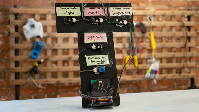
Our goal with this activity is to create a ‘hub’ (i.e. a central place where all the incoming information can be seen).
It’s important for us to label our different RGB LEDs to allow for easy readability by people who haven’t built the device.
Three red or green lights don’t mean anything to other people without labels, so let's build an easy way for someone else to use the interface we've created.
Crafting Supplies
- 3 labels
- 1 pen
- sticky tape or Blu-Tack
- 1 flat piece of board (8x30cm approx.)
Process
Our goal with this activity is to create a ‘hub’ (i.e. a central place where all the incoming information can be seen).
It’s important for us to label our different RGB LEDs to allow for easy readability by people who haven’t built the device.
3 Red / Green lights don’t mean anything to other people and so we need to state what their purposes are.
Instructions
- Take your flat piece of board and stick your 3 labels onto it, allowing enough room for each of the RGB LEDs to be fastened to the board.
- Use your pen to write “Light” on one label, “Temperature” on another label, and “Humidity” on the final label.
- Using your sticky tape or Blu-Tack, stick each RGB LED underneath the appropriate label (e.g. the RGB LED signifying the temperature level underneath the “Temperature” label. Also stick the micro:bit to the piece of board so that everything stays together.
- Make sure that all sensors and RGB LEDs are connected to the micro:bit correctly. If so, plug in the micro:bit to a power-source (either a laptop or battery pack). Now, it should be nice and obvious which light is related to which sensor!
-
In this lesson, we've combined a lot of our previous knowledge and hardware to create an environment sensor.
In the next lesson, we'll learn some new concepts and technologies, and use them to make an animal counter!